


Integrating a Linear Translation Assembly into Optical Cage Systems
Simple Translation | Ball Bearing Translation
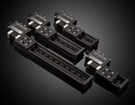
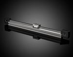
TECHSPEC Cage System Linear Translation Assemblies are used to add linear translation to TECHSPEC Optical Cage Systems. The built-in translation assembly enables coarse positioning along the cage rods. Once fixed to the cage rods, fine translation can be done using a micrometer drive. A single pair of springs offers ½” of translation. By adding additional #86-838 springs, the travel can be extended to 1". TECHSPEC Cage System Linear Translation Assemblies are available in two options:
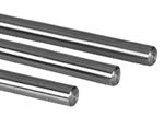
- #85-618 simple translation utilizes 6mm rods and standard plates
- #86-847 ball bearing translation utilizes ball bearings for low-friction translation
WHAT IS SIMPLE TRANSLATION?
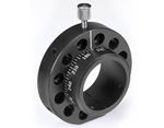
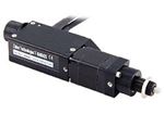
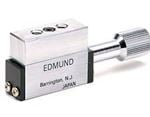
A #85-618 simple translation assembly can be built along two or more 6mm rods anywhere within an existing cage system. All simple translation assemblies require a #85-618 micrometer mount kit, which includes a micrometer holder, protective steel plate, and two compression springs. A micrometer or drive mechanism with a 3/8” shank is required and sold separately.
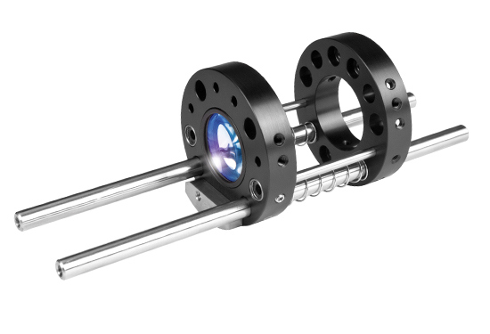
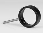
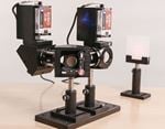
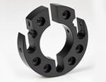
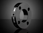
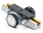
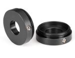
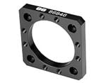
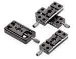
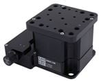
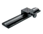
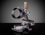
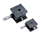
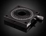
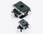
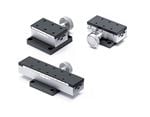
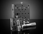
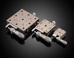
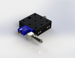
Any two standard cage plates can be used in the simple translation assembly (Figure 1). One plate is used to hold the optical component and translate along the rods. The second plate is fixed and used to keep the springs compressed. Alternatively, a pair of #86-845 shaft collars can be used in place of the fixed place (Figure 2). Note: To make integration easy, download a complete SolidWorks® assembly of the Simple Translation Assembly with Plates (ZIP 2.2MB), or the Simple Translation Assembly with Shaft Collars (ZIP 3MB).
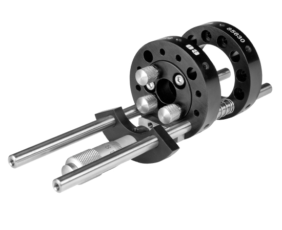
Figure 1: Simple Translation Assembly with Plates
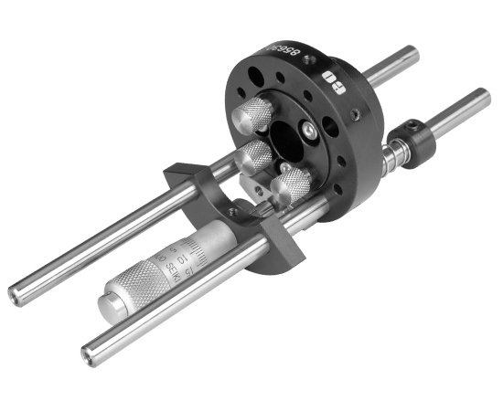
Figure 2: Simple Translation Assembly with Shaft Collars
Simple Translation Assembly
- Slide the fixed plate or shaft collars onto the 6mm rods. Keep this plate loose on the rods for now. A minimum of two rods is required.
- Add a spring after the fixed plate or collars to each of the two adjacent rods. A second spring can be added to the rods to increase the travel distance to 1” (Figure 3).
- Attach the protective steel plate to the translation plate with M3 SHCS. Slide the translation plate onto the rods so that the steel plate is positioned between the two rods with springs. Be sure the steel plate is facing away from the springs.
- Adjust the location of the translation plate until it is in the approximate desired location. It can be temporarily locked in place while the remaining assembly is completed (Figure 4).
- Use M3 set screws to secure the micrometer or drive mechanism shank within the micrometer holder. Adjust the micrometer or drive mechanism to the half extended position.
- Slide the micrometer holder onto the two rods with springs so that the shaft of the micrometer or drive mechanism is in contact with the steel plate. Secure the micrometer holder on the 6mm rods with M3 set screws.
- Compress the springs to approximately 3/4 of their uncompressed length by pushing the fixed plate toward the translation plate. Lock the fixed plate onto the rods while keeping the springs compressed.
- If the translation plate was locked in place in Step 4, loosen the screws to allow the translation plate to move freely. The translation plate should now move when the micrometer or drive mechanism is adjusted (Figure 5 and 6).
Figure 3: Rod and Spring Positions
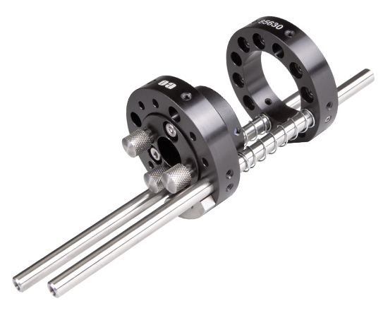
Figure 4: Simple Translation Assembly without Drive Mechanism
Figure 5: Video of Final Simple Translation Assembly with Plates
Figure 6: Video of Final Simple Translation Assembly with Shaft Collars
WHAT IS BALL BEARING TRANSLATION?
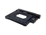
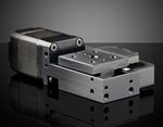
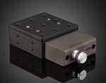
For added precision, ball bearing translation can be used to provide low-friction translation. A #86-847 ball bearing translation assembly can be built along two 6mm rods anywhere within an existing cage system. The ball bearing translation assembly kit includes:
- #85-618 the micrometer mount kit (which contains a micrometer holder, protective steel plate, and pair of springs)
- one #85-620 travel bearing plate
- one #85-619 fixed bearing plate
- two #85-686 linear bearing bushings
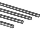
- two #85-470 50mm Long 3mm Rods
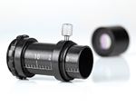
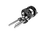
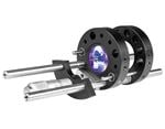
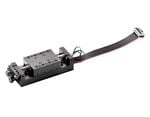
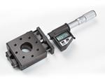
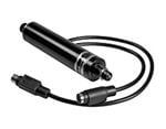
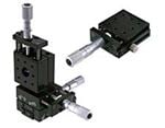
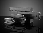
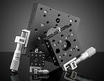
A complete ball bearing translation also requires a micrometer or drive mechanism with 3/8” shank (Figure7). Note: To make integration easy, download a complete SolidWorks® assembly of the Ball Bearing Translation Assembly (ZIP 2.9MB).
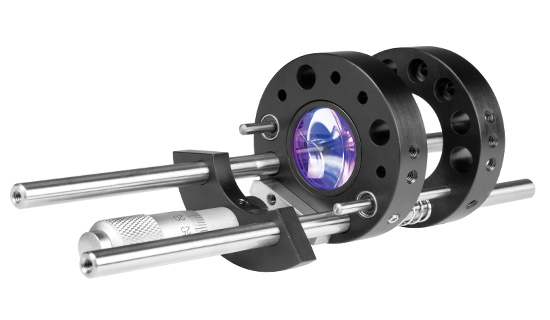
Figure 7: Ball Bearing Translation Assembly
Ball Bearing Translation Assembly
- Insert the two 3mm rods into the 3mm rod holes of the fixed bearing plate, keeping the ends of the rods flush with the back of the plate. Lock the rods in place with M3 set screws
- Slide the fixed plate onto two adjacent 6mm rods, while ensuring a 3mm rod is immediately above each 6mm rod. Keep this plate loose on the rods for now. Using more than two 6mm rods is not recommended. Add a spring to each of the 6mm rods. A second spring can be added to each rod to increase the travel distance to 1” (Figure 8).
- Insert the ball bearing bushings into the 7mm holes of the travel bearing plate, and lock into place with M3 set screws. Attach the protective steel plate to the translation plate below the bushings. Slide the translation plate onto the rods so that 3mm rods are inserted into the ball bearing bushings. Keep the steel plate positioned between the two 6mm rods, and facing away from the springs (Figure 9).
- Adjust the location of the translation plate until it is in the approximate desired location. It can be temporarily locked in place while the remaining assembly is completed.
- Use M3 sew screws to secure the micrometer or drive mechanism shank within the micrometer holder. Adjust the micrometer or drive mechanism to the half extended position.
- Slide the micrometer holder onto the two 6mm rods so that the shaft of the micrometer or drive mechanism is in contact with the steel plate. Secure the micrometer holder onto the 6mm rods with M3 set screws.
- Push the fixed plate toward the translation plate so that the springs are compressed to approximately 3/4 of their uncompressed length. Lock the fixed plate onto the 6mm rods while keeping the springs compressed
- If the translation plate was locked in place in Step 7, loosen the screws to allow the translation plate to move freely. The translation plate should now move when the micrometer or drive mechanism is adjusted (Figure 10).
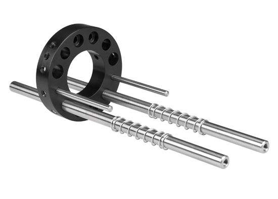
Figure 8: 3mm and 6mm Rod and Spring Positions


weitere regionale Telefonnummern
ANGEBOTSTOOL
Geben Sie zum Starten die Produktnummer ein.
Copyright 2023 | Edmund Optics Inc. vertreten durch Edmund Optics GmbH, Isaac-Fulda-Allee 5, 55124 Mainz, Deutschland
Die Edmund Optics GmbH Deutschland fungiert als Handelsvermittler für die Edmund Optics Ltd. in Großbritannien.
Vertragspartner ist die Edmund Optics Ltd. in Großbritannien.