


Optical Cage System Design Examples
Designed for modularity and flexibility, optical cage systems are high precision alternatives to complex optical alignment systems. These systems are constructed of rods and plates, allowing the user to continuously modify the system's design by adding additional components, such as optical mounts and angular brackets. For the complete line of components, browse TECHSPEC® Optical Cage System.
For an introduction to what can be done with optical cage systems, consider seven unique design examples. Each design can be applied toward larger systems, and provide familiarity to the cage system. For example, Figure 1 illustrates a sample system comprised of four stock numbers: #85-632 25mm Standard Cage Plate, #85-664 Cage Plate Angle Bracket, #85-488 6mm Diameter x 100mm Length Cage Support Rod, and #85-543 25mm Cage 20mm Diameter Lens Mount.
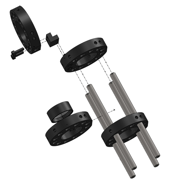
Note: These stock numbers are only one sample setup; components can be replaced with those of different sizes.
Optical Cage System Design Examples Include
- Cube
- Angle Bracket Joints
- Skeletal Rails
- Swivel Joint
- Bent Elbow Telescope
- Interchangeable Optical Mount
- Retaining Ring Pair
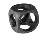
DESIGN EXAMPLE 1: OPTICAL CAGE SYSTEM CUBE
The optical cage system cube is a fundamental design that enables the addition or intersection of beam paths, or bends the system in 90°. While a TECHSPEC® Cage System Sphere is superior in rigidity, the cube system offers increased flexibility, and can be designed using Cage System Plates and Cage System Plate Angle Brackets. By using plates of different inner diameters, the cube system can be customized to best fit the application. For example, Figure 2 shows a cube system consisting of six #85-632 25mm Standard Cage Plates and eight #85-664 Cage Plate Angle Brackets.
Note: Do not tighten adjustment screws fully until all cage system components are attached. To make integration easy, download a complete SolidWorks® assembly of Design Example 1 (ZIP 1.1MB).
DESIGN EXAMPLE 2: OPTICAL CAGE SYSTEM ANGLE BRACKET JOINTS
Similar to the build of the cube system in Design Example 1, it is possible to create joints angled at 30°, 60°, and 90°. Due to their diverse use in many setups, angle brackets are crucial components in a variety of cage system setups. All 30°, 60°, and 90° angles can be created with two Cage System Plates (such as #85-632), two #85-617 25mm Fixed Angle Mounting Plates, and four #85-664 Cage Plate Angle Brackets. To make integration easy, download a complete SolidWorks® assembly of Design Example 2 (ZIP 1.5MB).
Figure 2: Video of Optical Cage System Cube
Figure 3: Video of Optical Cage System Angle Bracket Joints
DESIGN EXAMPLE 3: OPTICAL CAGE SYSTEM SKELETAL RAILS
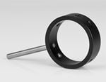
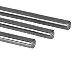
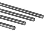
Building from Design Example 2, skeletal rails can be added to connect the cube system or angle bracket joints. When joining numerous joints and components together, use TECHSPEC® 6mm Cage System Support Rods to hold the optical axis in place. A cage system can be built with either two or four rods. A four rod system adds additional stability for long systems, while two rods simplify assembly and allow easy access to the optical components within the cage.
When connecting 6mm Cage System Support Rods to Cage System Plates, it is best to lay each plate on a flat surface such as a laboratory table and connect each support rod into the appropriate sized holes. Then, use a set screw to secure the support rods in place. To make integration easy, download a complete SolidWorks® assembly of Design Example 3 (ZIP 1.1MB).
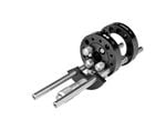
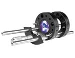
DESIGN EXAMPLE 4: OPTICAL CAGE SYSTEM SWIVEL JOINT
TECHSPEC® Cage System Angle Adjustment Plates are used to construct fixed 30°, 60°, and 90° bends in a cage system's optical path. For applications requiring customized angular positions, swivel joints are an ideal alternative to angle adjustment plates. For example, a pair of #85-670 Swivel Adapter Plates can be used with a single #85-692 Post Mount Adapter to enable 180° of continuous angular adjustment. Each swivel adapter plate features three M3 set screws which allow the angle to be locked into place. For this design example, the swivel joint consists of two #85-632 Cage System Plates, four #85-670 Swivel Adapter Plates, two #85-692 Post Mount Adapters, eight #85-488 6mm Diameter x 100mm Length Support Rods, and two #85-664 Cage Plate Angle Brackets. To make integration easy, download a complete SolidWorks® assembly of Design Example 4 (ZIP 2MB).
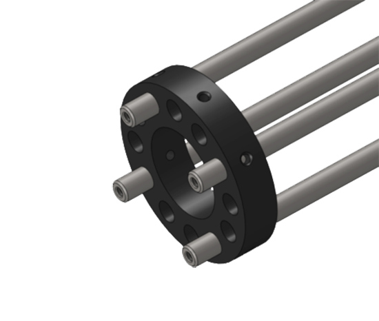
Figure 4: Illustration of Optical Cage System Plate with Four 6mm Support Rods
Figure 5: Video of Optical Cage System Swivel Joint
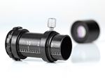
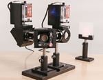
DESIGN EXAMPLE 5: OPTICAL CAGE SYSTEM SPECTROSCOPE
Another practical use of an optical cage system is to build a spectroscope from the structure outlined in Design Example 4. In addition to a swivel joint, the spectroscope also needs two Cage System Optical Mounts (such as #85-543), one more lens mount to hold #58-544 100μm x 3mm Mounted Precision Air Slit (such as #85-543), and one prism.
To accurately see the spectra produced by the prism, secure the two lenses onto the arm. For a Keplerian-design spectroscope, keep in mind that the Cage System Plates are the focal length of lens 1 and 2 combined. Secure the plates into place along the rails by a set screw. Using a retaining ring, mount the lenses into the lens mounts. Then, connect the mounts in their respective plate inner diameter, and secure with set screws.
The second arm contains two Cage System Plates that are used to direct a light source through the prism. The outermost plate holds a fiber adapter piece that secures a fiber optic. The second plate holds a 100μm x 3mm Precision Air Slit, which uses a lens mount to secure the slit. This lens mount then slides into place and secures with a set screw. The swivel joint is ideal because the arm containing the spectroscope can be positioned at different angles, ensuring access to the prism's full spectrum without any clipping.

Figure 6: Illustration of Optical Cage System Bent Elbow Telescope
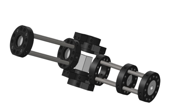
Figure 7: Illustration of Optical Cage System Spectroscope
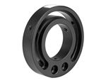
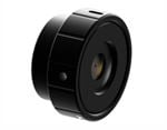
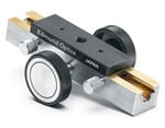
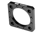
DESIGN EXAMPLE 6: OPTICAL CAGE SYSTEM INTERCHANGEABLE OPTICAL MOUNT
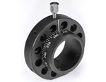
Connecting #85-717 25mm Interchangeable Optic Mount with #85-641 30mm Side Access Mounting Plate simplifies adding or removing optical components within a cage system. The 60° cutout in the mounting plate enables the optic mount to easily slide in and out of place, avoiding disassembly and reassembly of the entire cage system. Use set screws to secure the mounting plate in the optic mount to create flexibility without loss of precision. This two-component assembly can be used with a variety of cage system setups. To make integration easy, download a complete SolidWorks® assembly of Design Example 6 (ZIP 963KB).
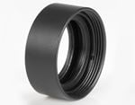
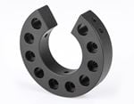
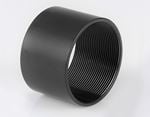
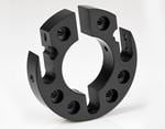
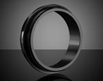
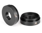
DESIGN EXAMPLE 7: OPTICAL CAGE SYSTEM RETAINING RING PAIR
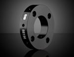
To mount an optical component such as a lens or filter into a Cage System Tube, use a pair of retaining rings. For example, use a tube with a 30mm outer diameter and length of 10mm (such as #85-589) as the outer tubing; then, match the retaining ring to the respective optic diameter. If the application uses a 25mm diameter optic, #85-597 retaining ring with a clear aperture of 23mm is the ideal choice.
To connect the components together, thread one retaining ring into the extension tube until the ring is in the desired position. Gently place the optic onto the retaining ring so that the face of the optic is in contact with the face of the retaining ring. Thread in the second retaining ring until it makes contact with the optic and holds it firmly in place.
Note: To avoid damage to the optic, do not over tighten the retaining ring. Similar to Design Example 6, the Optical Cage System Retaining Ring Pair is a crucial component to a variety of cage system applications. To make integration easy, download a complete SolidWorks® assembly of Design Example 7 (ZIP 324KB).
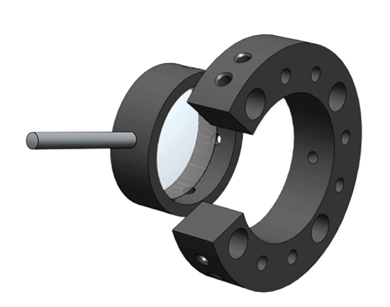
Figure 8: Illustration of Optical Cage System Interchangeable Optical Mount
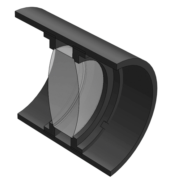
Figure 9: Illustration of Optical Cage System Retaining Ring Pair
The preceding seven design examples are just a few of the almost limitless number of structures that can be created with a TECHSPEC Optical Cage System. No matter the application or complexity of setup, the cage system offers a wide range of components. For an introduction to its flexibility, diversity, precision, and integration, read about all the cage system's capabilities.
weitere regionale Telefonnummern
ANGEBOTSTOOL
Geben Sie zum Starten die Produktnummer ein.
Copyright 2023 | Edmund Optics Inc. vertreten durch Edmund Optics GmbH, Isaac-Fulda-Allee 5, 55124 Mainz, Deutschland
Die Edmund Optics GmbH Deutschland fungiert als Handelsvermittler für die Edmund Optics Ltd. in Großbritannien.
Vertragspartner ist die Edmund Optics Ltd. in Großbritannien.