Beam Expander Testing
Laser beam expanders are used to increase a collimated input beam’s diameter for a wide range of laser applications. When characterizing the quality of a laser beam expander, it is critical to test its transmitted wavefront error or the deviation of the wavefront leaving the laser beam expander from its ideal shape. Analyzing transmitted wavefront error determines how aberrations affect the performance of the laser beam expander.
A wavefront is a surface over which an optical wave has a constant phase. Because wavefronts are perpendicular to the wave’s direction of propagation, planar wavefronts are associated with collimated light and curved wavefronts are associated with converging or diverging light (Figure 1). Aberrations in optical components result in distortions in transmitted or reflected wavefronts, known as transmitted or reflected wavefront error.

Figure 1: Perfectly collimated light entering the lens has a planar wavefront, while light-converging after a perfect, aberration-free lens will have a spherical wavefront centered at the focused spot
A Shack-Hartmann wavefront sensor (SHWFS) is typically used to measure transmitted wavefront error in laser beam expander testing with high dynamic range and accuracy. A SHWFS is comprised of an array of identical microlenses, or lenslets, which each focus portions of incident light onto a small sector of a detector array (Figure 2).
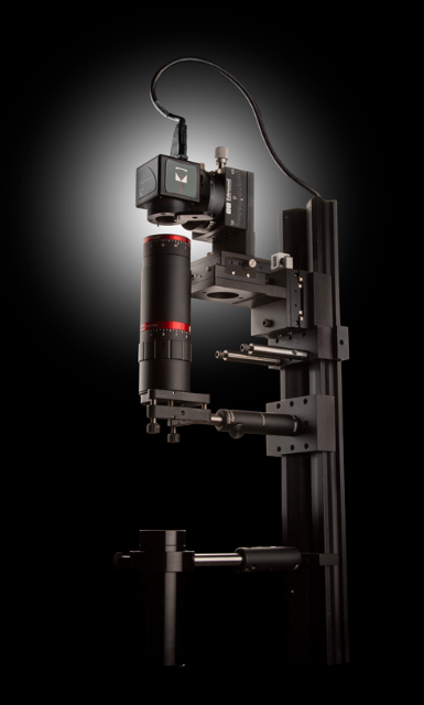
Figure 2: Shack-Hartmann wavefront sensors are widely used for testing the transmitted wavefront error of beam expanders because of their fast response, ease of use, and relatively low cost
A perfectly collimated incident wave with a planar wavefront would be focused into a grid of focused spots separated by the distance between the centers of each of the microlenses. An incident wave containing wavefront error will result in a change in the position of the focused spots on the detector (Figure 3). This displacement, or a decrease in intensity at the focused spots, is used to determine the localized tilt of the wavefront incident on each of the microlenses in the array. The individual tilts are then used to approximate the full incident wavefront.
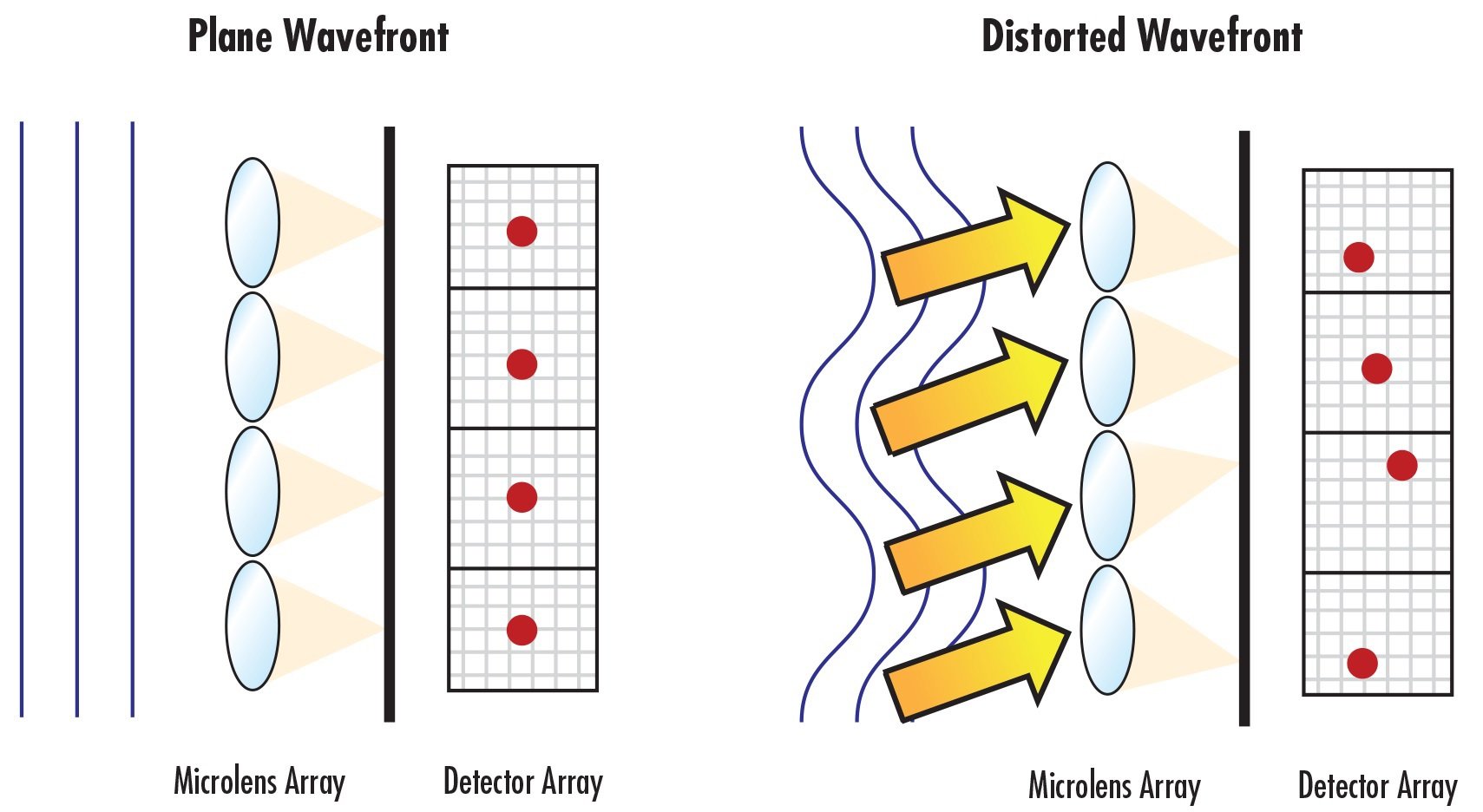
Figure 3: Wavefront error in an incident optical wave entering a SHWFS will result in displacements of the focused spot positions on the detector array
In general, the focused spot from each microlens should cover ten or more pixels on its respective sensor segment in order to accurately reconstruct the incident wavefront. The sensitivity of the SHWFS improves as the detector area covered by the focused spot increases. However, this comes with a tradeoff of shorter dynamic range. As a rule of thumb, the focused spot of each microlens should not cover more than half of its associated sensor segment for a reasonable compromise between sensitivity and dynamic range.1
The amount of data points captured can be multiplied by increasing the number of microlenses in the array, reducing the amount of averaging of the wavefront slope that must be performed. However, increasing the number of microlenses also reduces the amount of pixels allocated to each microlens. A smaller amount of larger microlenses may not adequately sample complex wavefronts and can lead to an artificial smoothing of the reconstructed wavefront, but larger microlenses produce a more precise and sensitive measurement of slowly varying wavefronts.2 All of these tradeoffs must be considered when testing laser beam expanders.
The transmitted wavefront of laser beam expanders is specified as an amount of waves. For example, if a laser beam expander designed for 532nm has a P-V (peak-to-valley) transmitted wavefront error of λ/10, then the maximum amount of allowed distortion from an ideal output wavefront is given by:
Laser beam expanders are generally considered to be “diffraction-limited” if they have a transmitted wavefront error of λ/4.
| Beam Expander Theory | Beam Expander Selection Guide | Rotating vs. Sliding Beam Expander Divergence Adjustment |
| LEARN MORE | LEARN MORE | LEARN MORE |
References
- Forest, Craig R., Claude R. Canizares, Daniel R. Neal, Michael McGuirk, and Mark Lee Schattenburg. "Metrology of thin transparent optics using Shack-Hartmann wavefront sensing." Optical engineering 43, no. 3 (2004): 742-754.
- John E. Greivenkamp, Daniel G. Smith, Robert O. Gappinger, Gregory A. Williby, "Optical testing using Shack-Hartmann wavefront sensors," Proc. SPIE 4416, Optical Engineering for Sensing and Nanotechnology (ICOSN 2001), (8 May 2001); doi: 10.1117/12.427063





weitere regionale Telefonnummern
ANGEBOTSTOOL
Geben Sie zum Starten die Produktnummer ein.
Copyright 2023 | Edmund Optics, Ltd Unit 1, Opus Avenue, Nether Poppleton, York, YO26 6BL, UK
Die Edmund Optics GmbH Deutschland fungiert als Handelsvermittler für die Edmund Optics Ltd. in Großbritannien.
Vertragspartner ist die Edmund Optics Ltd. in Großbritannien.