Building and aligning a four-mirror beam path with two-point beam walking
Adapted from the Lawrence Livermore National Laboratory Laser Safety Office’s Laser & Optical Alignment Training and Laser User Alignment and Reference Guide, Version 2.1
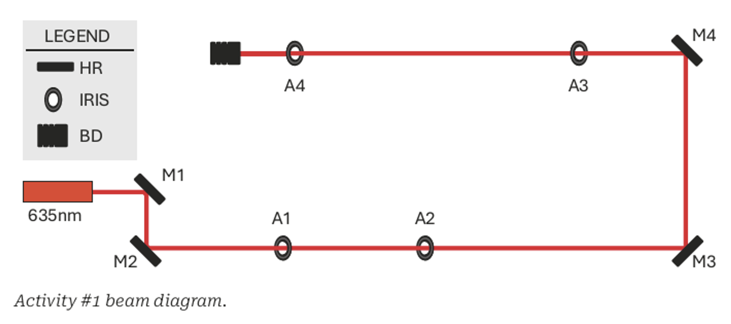
Figure 1: Activity #1 beam diagram. A 635 nm alignment laser is directed by high reflective (HR) mirrors M1-M4 through irises A1-A4 and terminated at the beam dump (BD). Diagram adapted from the LLNL Laser Safety Office training manual.
LEARNING GOAL
Align and recover a defined optical axis
LASER SOURCE
1 mW, 635 nm visible diode laser
CORE SKILL
Two-point beam walking with kinematic mirrors
Learning Objectives for Laser Beam Alignment
Activity #1 teaches a foundational alignment method: using two adjustable mirrors to steer a laser beam through two fixed apertures that define an optical axis. The procedure is then repeated with a second mirror-and-iris pair to extend the aligned path across the breadboard.
After completing the activity, the learner should be able to:
Establish a constant beam height parallel to the optical table.
Use two irises as fixed references for an optical axis.
Walk a beam through two apertures by alternating adjustments between two mirrors.
Recover downstream alignment after intentionally disturbing the upstream mirrors.
This application note is an educational supplement and is not a substitute for approved laser safety training, a laboratory-specific standard operating procedure, or guidance from the responsible Laser Safety Officer. The BOM specifies a 1 mW, 635 nm visible laser, but users must still control the beam, avoid direct or specular viewing, remove reflective objects, secure the beam block, restrict access, and follow all local requirements. Determine protective eyewear and other controls through the applicable risk assessment and site procedures. Ensure Allen keys and other tools do not intercept the beam during alignment, or turn off the laser before securing components.
How Laser Beam Alignment Using Two-Point Beam Walking Works
Two irises placed at different positions define a straight optical axis. A single mirror can place the beam on one iris, but it cannot independently control both beam position and propagation angle. A pair of tip/tilt mirrors provides the two control points needed to center the beam on both irises.
In the first section of the activity, mirror M1 primarily changes where the beam arrives at the downstream reference while mirror M2 steers the beam through the near and far apertures. The adjustments are coupled, so the learner alternates between the two mirrors until the beam remains centered at both irises A1 and A2. The same method is then applied to mirrors M3 and M4 as well as irises A3 and A4.
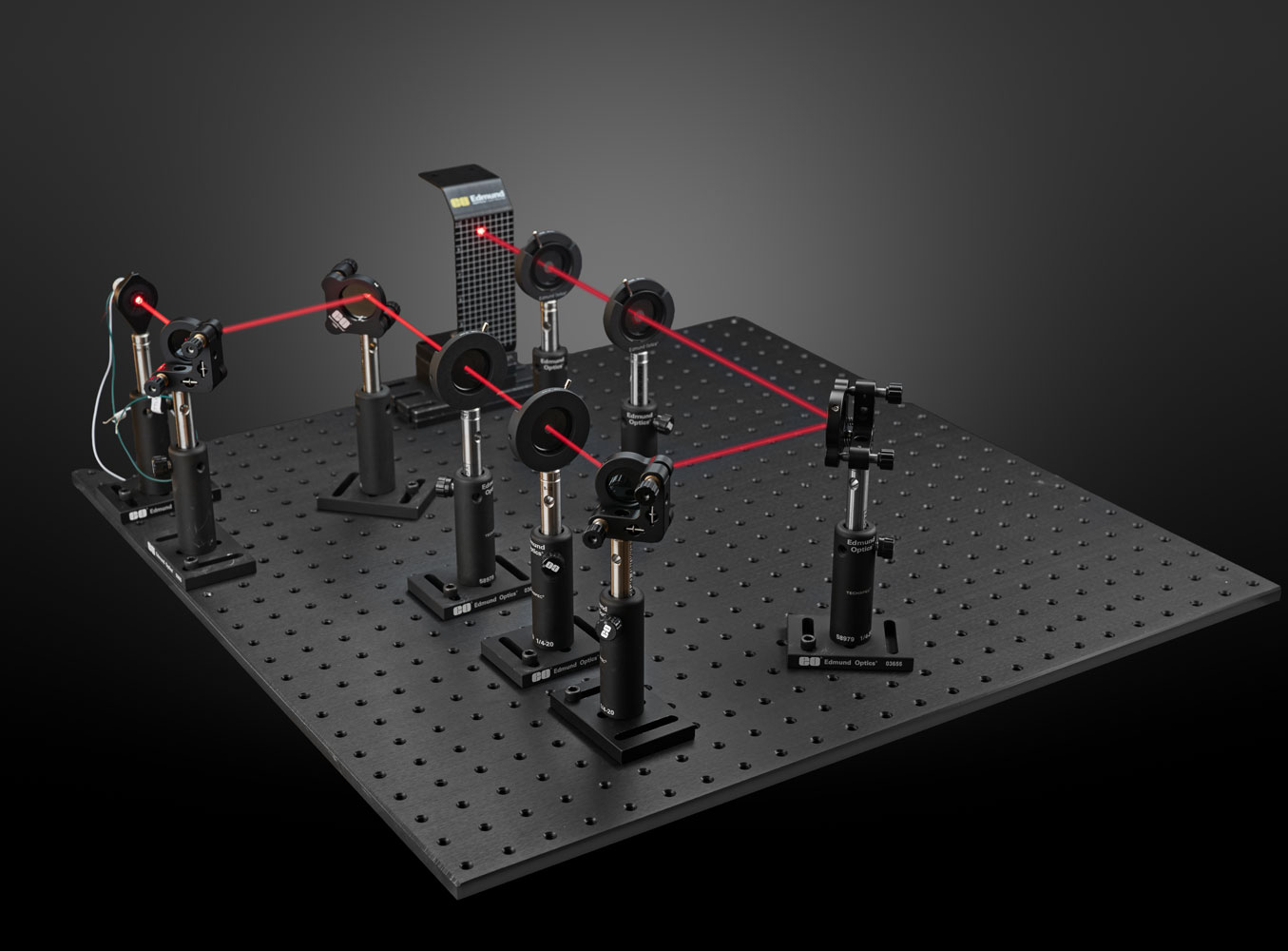
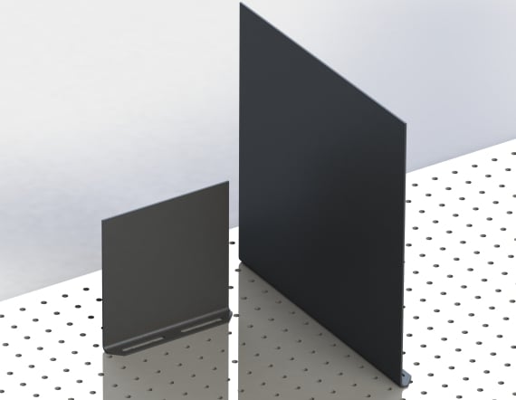
Figure 2: Physical implementation of the Activity #1 setup on an Edmund Optics breadboard. Protective barriers shown are site-specific and are not included in the BOM.
Edmund Optics® Components Required for the Laser Alignment Setup
The following bill of materials supports one complete Activity #1 setup. The breadboard and screw kit are included to make the list practical for a new or dedicated training station.
How to Set Up the Four-Mirror Laser Alignment System
Place the breadboard in a controlled work area. Install any required barriers or perimeter guards before energizing the laser.
Remove watches, jewelry, dangling badges, reflective tools, and unnecessary items from the work area. Confirm that only trained and authorized participants are present. Assemble the laser, four kinematic mirror mounts, and four mounted irises on posts and post holders. Use a beam-height gauge to set the center of every optic to the same height. Ensure that the laser is securely mounted approximately parallel to the breadboard. If the laser has focus adjustment (the one in the BOM does), ensure that it is focused so that it’s approximately collimated (smallest beam diameter).
Arrange the components to match Figure 1. Keep each beam segment horizontal and parallel to the breadboard surface. Position M1 and M2 near the laser, followed by A1 and A2. Place M3 and M4 at the far end, followed by A3 and A4 on the return path.
Place the beam block after A4 so every intended beam path terminates on a rated, secured surface. During coarse setup, add temporary blocks behind the optic being adjusted to capture stray beams.
With the laser blocked or off, rotate each mirror mount so the planned reflections are approximately 90° and the beam will strike near the center of every mirror and iris.
Step-by-Step Laser Beam Alignment Procedure
Part A – Align Mirrors M1 and M2 Through Irises A1 and A2
Set A1 and A2 to the common beam height and secure their bases. These two fixed apertures define the first optical axis.
Position M1 so the laser strikes near the center of the mirror and reflects toward M2. Secure M1 to the breadboard.
Position M2 so the beam from M1 strikes near its center and is directed approximately along the axis through A1 and A2. Secure M2.
Close A1 to a small opening. Use the tip/tilt adjusters on M1 to center the beam on A1.
Open A1 and close A2. Use the tip/tilt adjusters on M2 to move the beam toward the center of A2.
Return to A1 and check the beam position. Alternate between M1/A1 and M2/A2, making progressively smaller adjustments, until the beam passes through the center of both irises.
BEAM-WALKING TIP
When correcting one axis, use M1 to move the spot at the far iris beyond the desired point, then use M2 to bring it back. Repeat until both the near and far irises are centered. Complete the horizontal correction first, then the vertical correction.
Part B – Extend the Optical Axis Through Irises A3 and A4
Position M3 so the beam exiting A2 strikes near the center of the mirror and is redirected toward M4.
Position M4 so the beam is directed approximately along the axis through A3 and A4.
Close A3 and use M3 to center the beam on A3. Then open A3, close A4, and use M4 to center the beam on A4.
Alternate between M3/A3 and M4/A4 until the beam passes through the center of both irises and terminates on the beam block.
Part C - Recovering Laser Alignment After Intentional Misalignment
Record or mark the positions of A1 and A2. Do not disturb M3, M4, A3, or A4.
Intentionally misalign M1 and M2 so the beam no longer passes through A1 and A2.
Repeat the Part A beam-walking procedure until the beam is again centered through A1 and A2.
Verify that the beam has also returned through A3 and A4. Successful recovery demonstrates that two fixed control points define the beam’s downstream propagation direction, provided the downstream optics remain unchanged.
Observation
Recommended Check
Beam centers on A1 but misses A2
Continue alternating M1 and M2 rather than trying to correct the far iris with M2 alone.
Beam height changes along the path
Recheck post heights and confirm each beam segment is parallel to the breadboard.
Beam clips a mirror or iris
Reposition the mount so the beam strikes the optic near its mechanical center before fine adjustment.
Downstream alignment does not recover
Confirm M3, M4, A3, and A4 were not moved and that A1/A2 returned to their original positions.
Unexpected secondary spot appears
Block the main beam and search for specular reflections from mounts, tools, barriers, and optic surfaces. Terminate all unused beams.
Post Laser Beam Alignment Verification and Safety Checklist
Confirm the beam is centered through A1-A4 and fully intercepted by the beam block.
Secure mirror locks, post holders, bases, and the beam block without changing alignment.
Search for and terminate stray or unused reflections.
Restore all barriers, covers, enclosures, warning controls, and interlocks required by the laboratory.
Communicate the system status to everyone in the area before changing operating conditions.
Leave the irises in place as alignment references or document their exact locations for repeatable reinsertion.
Edmund Optics gratefully acknowledges the Lawrence Livermore National Laboratory Laser Safety Office for developing the laser alignment training program, exercises, and supporting guidance that informed this application note. This document is an independent Edmund Optics adaptation and should not be interpreted as replacing LLNL training, local procedures, or Laser Safety Officer oversight.
Reference
Lawrence Livermore National Laboratory Laser Safety Office, Laser User Alignment and Reference Guide, Version 2, LLNL-TM-2016217, Chapter 9 and Chapter 10, Activity #1.
War dieser Inhalt nützlich für Sie?
Please select your shipping country to view the most accurate inventory information, and to determine the correct Edmund Optics sales office for your order.










weitere regionale Telefonnummern
ANGEBOTSTOOL
Geben Sie zum Starten die Produktnummer ein.
Copyright 2023 | Edmund Optics, Ltd Unit 1, Opus Avenue, Nether Poppleton, York, YO26 6BL, UK
DATENSCHUTZRICHTLINIE | COOKIE POLICY | AGB | AGB FÜR B2C | IMPRESSUM | BARRIEREFREIHEIT
Die Edmund Optics GmbH Deutschland fungiert als Handelsvermittler für die Edmund Optics BV in den Niederlanden.
Vertragspartner ist Edmund Optics BV in den Niederlanden.
This content may include material that has been generated or modified using artificial intelligence (AI).
The FUTURE Depends On Optics®